The heat transfer coefficient is the most important factor in heat exchanger design. Metals and metal alloys have the highest heat transfer coefficients in the world. For this reason, the tubes and plates used in heat exchangers — i.e. all components of the thermal system — are selected from this material group. AISI 316, AISI 304 and Titanium are the most popular materials in the heat exchanger industry.
In most heat exchangers there are no external thermal or mechanical interactions. A typical system operates by evaporating and condensing single- or multi-component fluid streams while heating or cooling another fluid. While one side gives off heat, the other absorbs it. Other applications include heat recovery, sterilisation, fluid condensation and process control.
1. Classification of Heat Exchangers
Heat exchangers operate according to the laws of thermal systems, transferring thermal energy (enthalpy) from one fluid to another. Typical applications include heating and cooling as well as the evaporation or condensation of single- or multi-component fluids.
Heat transfer generally takes place on the surfaces of thin plates or tubes that separate the fluids. These walls prevent the fluids from mixing while providing better control over the hot and cold media. Heat exchangers in which the fluids are separated by plates or tubes are called "plate heat exchangers" or "U-tube heat exchangers".
The key point in any heat exchanger is that it is designed to transfer heat from one fluid to another and complies with the laws of thermodynamics. The most common types are shell-and-tube and plate heat exchangers.
1.1. Fixed-tube Heat Exchanger
In this model, additional fins are used to enlarge the heat-conducting surface of the tubes; they are welded in place, reduce cost and increase efficiency. However, the tube bundles cannot be removed.
1.2. Removable Tube Bundles
To ensure long-term use of the product or to define the position of the fluid, tube bundles can be removed, cleaned and reassembled on request. The easiest solution to clogging is to remove and clean the tubes; after careful inspection they can be replaced or refitted.
1.3. Straight-tube Heat Exchangers
Clamps hold the tube bundles together. The other side is in full contact with the fluid and remains free. The floating part is bolted to the shell surface, thereby preventing leakage and tube deflection. This type transfers enthalpy directly; the stored thermal energy is dissipated across the entire heat-conducting area or matrix. Examples include boilers, radiators, cooling towers and condensers.
1.4. Plate Heat Exchangers
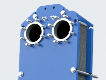
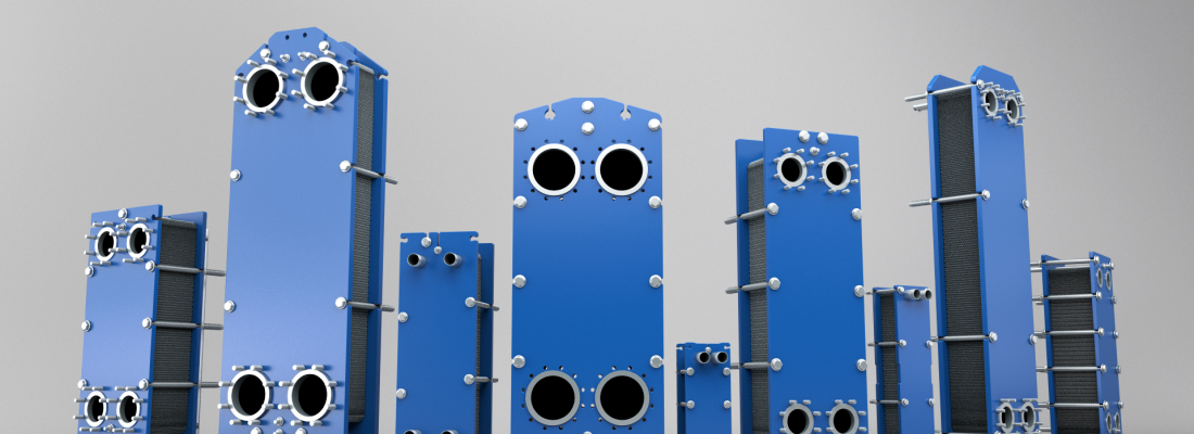
Plate heat exchangers consist of two metal plates joined together, forming a system of narrow channels and plastic gaskets. The corners of the large-surface plates form the inlet and outlet points of the flow, while the matrix pattern and pathways between the plates increase the heat transfer area. The fluids absorb or release heat across the surfaces they pass over. Dividing the plates into channels enables heat transfer between hot and cold media without mixing. Owing to their large heat transfer areas, they are preferred over other exchanger types.
1.5. Regenerative Heat Exchangers
In regenerative heat exchangers the same fluid passes through both sides of the exchanger; this is possible in both plate and tube exchangers. The system allows the fluid to reach very high temperatures, and the outlet fluid is generally used to cool the other. Because they operate cyclically, almost all the heat from the outlet fluid is transferred and cooling is achieved. Only a small amount of energy is needed to reach a steady temperature.
1.6. Adiabatic Cylindrical Heat Exchangers
In this type the second fluid is the central medium that fully contacts the tubes through which the first fluid flows, thus enabling heat transfer. The tubes arranged in a circular pattern create a large heat transfer area within the second fluid.
Classification by Function
By Number of Fluids
- 2 fluids
- 3 fluids
- N fluids
By Heat Transfer Mechanism
- Two-sided single-phase convection
- One-sided single-phase convection
- Two-sided two-phase convection
- Combined convection and radiation
By Heat Transfer Process
- Direct contact
- Gas-liquid
- Liquid-vapour
- Immiscible
- Indirect contact
- Direct transfer
- Storage type
- Fluidised bed
By Surface Compactness
- Gas-to-liquid
- Compact (β > 700 m²/m³)
- Non-compact (β < 700 m²/m³)
- Liquid-to-liquid
- Compact (β > 400 m²/m³)
- Non-compact (β < 400 m²/m³)
By Construction
- Tubular
- Double-pipe
- Spiral tube
- Coiled tube
- Shell-and-tube
- Plate
- Welded
- Gasketed
- Brazed
- Spiral
- Printed
- Plate coil
- Extended surface
- Plate-fin
- Tube-fin
- Regenerative
- Rotary
- Fixed matrix
- Rotating plate
By Fluid Flow Arrangement
- Single-pass
- Counter-flow
- Cross-flow
- Split-flow
- Multi-pass
- Extended surface
- Plate
- Shell-and-tube
Design: Area, Fins and Connections
The efficiency of heat exchangers depends on heat-transmission factors — matrix pattern, heat distribution methods, nozzles, manifolds, tanks, pipes and sealing elements. The most important of these is the heat transfer area: the larger the contact surface of the fluids, the higher the heat transfer. Maximising the surface area is therefore the central design objective.
On the other hand, heat distribution elements must be insulated to prevent heat loss and thereby increase system efficiency. Nozzles, head connections and similar parts must be tightened to the correct torque and assembled properly. Otherwise the safety of the thermal system decreases, the fluids may mix, and pressure losses occur. Operation manuals provide the basic reference for maintenance, repair and correct use. Apart from the rotary models of regenerative exchangers, most exchangers have no moving parts; rotating models use motors to increase pressure and flow rate.
A small contact area between the interfaces is sufficient to initiate heat transfer — this is called direct surface permeability. Another method to increase heat transfer is the use of fins. Fins are typically attached perpendicular (90°) to the surface and enlarge the transfer area, delivering more heat transfer at the same temperature. As a side effect they cause convection on the surface, dissipate heat via radiation and can lead to condensation on the shell. As a result, the thermal resistance of the surface decreases.
Fins also increase the structural strength of the matrix, allowing users to handle denser and more viscous fluids. The spacing between fins affects the temperature distribution: wider spacing reduces theoretical efficiency but lowers instantaneous pressure and ensures continuous circulation.
Naming Criteria
Heat exchangers are named in several ways: according to the heat transfer process, the number of fluids, the transmission mechanism, the type of construction and the flow arrangement. Another criterion is the heat transfer / volume ratio; compact exchangers are smaller, more practical models in this respect. Industry of use, component types and design parameters also lead to different names. The fluid type (gas-gas, gas-liquid, liquid-liquid) is another common classification criterion.
2. Heat Transfer Process
The heat transfer process is mainly used to distinguish between direct and indirect exchangers. In direct exchangers, heat transfer occurs through the mixing of fluids — cooling towers operate on this principle. In indirect exchangers, the fluids do not mix; heat transfer takes place via the surfaces that separate them.
2.1. Plate Heat Exchangers
Plate heat exchangers consist of plates with an embossed matrix pattern and a frame. The plates, usually pressed from stainless steel, are particularly suitable for the hygiene-sensitive food industry.
The active plate geometry enables the matrix design and maximises system efficiency, which broadens the range of applications. Combined with easy cleaning and maintenance, plate heat exchangers are the most widely used model worldwide. In demanding applications they stand out as an alternative to other types. Their working principle is natural thermal conduction. Design parameters vary: plate type (narrow or wide-area), plate grade (AISI 304, AISI 316, Titanium) and the number of plates are selected according to the application. Compared to shell-and-tube exchangers, their design and calculations are simpler.
2.2. Advantages and Disadvantages of Plate Heat Exchangers
Advantages:
- The counter-flow arrangement is favourable and allows a smaller heat transfer area.
- The different plate designs offer wide flexibility in thermal efficiency.
- The fluid flows turbulently across the matrix surface between the plates, increasing heat transfer.
- Since only the edges of the plates are exposed to the atmosphere, no additional insulation is required.
Disadvantages:
- Achieving high flow rates with low-pressure gases and fluids is difficult.
- Not suitable for very high pressures: the gaskets used for sealing are damaged at high pressure and temperature.
Thermal efficiency depends directly on the matrix design and on the properties of the fluid flowing across the matrix surface. The direction of the counter-flow and the layout of the thermal matrix area, as well as a narrow or wide matrix length, are the key parameters that determine the performance of a plate heat exchanger in a given application.
2.3. Pressure Drop Analysis
General system assumptions:
- The exchanger operates in a steady-state regime.
- Heat losses through the shell or frame are very small and can be neglected.
- No external thermal energy source is required.
- In parallel and counter flows, instantaneous temperature values are regular.
- The thermal resistance constant does not change across the exchanger.
- There is no phase change of the fluids throughout the exchanger.
- If the system is leak-free, heat transfer progresses in a balanced manner.
- Time-independent constant temperature and position values ensure both global and local heat transfer.
- The flow must be steady and isothermal; fluid properties are independent of time.
- Inlet and outlet temperatures of the fluid affect only characteristic properties such as density.
- Pressure points are independent of the fluid flow direction.
- The external forces acting on the exchanger are only gravity and — where present — electric and magnetic fields.
- According to Bernoulli's principle, the flow must occur along the streamline.
- Surface friction (surface roughness) is assumed equal throughout the matrix.
Components of the pressure drop:
- For incompressible fluids, pressure losses are proportional to surface friction and flow path.
- Fluid pressure drop is directly related to the heat transfer coefficient, operation method, plate size and mechanical properties of the material.
- Pressure losses can be calculated from exchanger properties: total loss along the matrix, inlet–outlet pipe connections, heads and manifolds; constrictions at the connections also cause pressure drops.
Conclusion
Thanks to their design flexibility and capacity for further development, heat exchangers can be designed according to the user's requirements, with adjustable heating and cooling temperature ranges. These characteristics lead to their widespread use in energy, petrochemicals, logistics, ventilation and cooling sectors.